3 Wire Speed Sensor Crank Sensor Wiring Diagram

Dbw To Dbc Conversion 03 Harnesses Wiring Diagram Collection Inside Throttle Position Sensor Wiring Diagram Sensor Diagram Throttle

How To Test The Crankshaft Position Sensor 1994 2004 3 0l V6 Mitsubishi Montero Map Sensor Automotive Mechanic Sensor

How To Test The Throttle Position Sensor 3 0l Mitsubishi Montero In 2020 Sensor Throttle Car Mechanic

1992 Toyota Corolla Electrical Wiring Diagram And Wiring Diagram For Toyota Corolla Types Of Electrical In 2020 Toyota Corolla Toyota Electrical Wiring Diagram

Electrical Wiring Diagram Of Motorcycle Http Bookingritzcarlton Info Electrical Wiring Diagram Of Electrical Wiring Diagram Fuel Injection Motorcycle Wiring
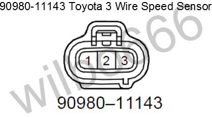
Wilbo666 Toyota Speed Sensors

Crank sensor wiring diagram wiring diagram images gallery pdf how to test a wheel speed sensor in under 15 minutes pdf related file of nissan speed sensor wire diagram.
3 wire speed sensor crank sensor wiring diagram. Both wires connect the vss to your vehicle to ground the sensor and transmit information about you re vehicle s speed. Sensor signal wire is a tn yl wire goes from pcm to cam sensor tn yl is tan with yellow tracer sensor ground and 5 v supply are as above but instead of crank sensor insert cam sensor. I am having similar problems on my 91 ram l cummins according to the wiring diagrams the diesel and gasser tanks have the same wires coming off the sending unit but one of the wires has dissimilar functions on a gasser it goes to the fuel pump on a diesel it. 3 wire hall effect sensor.
4 crankshaft position sensor wiring diagram you should pay attention to crankshaft position sensor symptoms. This is a image galleries about 3 wire hall effect sensor you can also find other images like wiring diagram parts diagram replacement parts electrical diagram repair manuals engine diagram engine scheme wiring harness fuse box vacuum diagram timing belt timing chain brakes diagram transmission diagram and engine problems. Wiring diagram for horn turn signal kit included. Disengage the wiring harness connector from the vss.
Knock sensor wiring diagram get rid of wiring diagram problem pdf p0019 crankshaft position camshaft position bank 2 sensor pdf part 2 how to test the 24x crank sensor gm 3 1l 3 4l pdf. This service manual is designed primarily for use by certified polaris master service dealer ranger rzr xp service manual the engine serial number can be found on a decal applied to the crankcase on the front.

E9 Engine Bay Diagram In 2020 Diagram Design Bmw E46 Bmw I

Stock Photo Honda Wiring Diagram Maxresdefault For Honda Wiring Diagrams Honda Wiring Diagram Bookingritzcarlton Info Honda Accord Honda Civic Honda

Inductive And Hall Effect Rpm Sensors Explained Kiril Mucevski Linkedin Hall Effect Sensor Automotive Electrical

Zafira Engine Bay Diagram Di 2020 Taurus Ford Diagram

Pin On Auta

Gm Throttle Position Sensor Wiring Library Of Wiring Diagram Pertaining To Throttle Position Sensor Wiring Diagram Positivity Sensor Throttle

Engine Compartment And 2002 Hyundai Accent Wiring Diagram With Dash Fuse Box Wiring Diagram Hyundai Accent Hyundai Hyundai Cars

Vn 2366 Diagram In Addition Crankshaft Position Sensor Location As Well As Bmw Download Diagram

7 Honda Accord Ex Engine Diagram Di 2020

Toyota Vios Engine Wiring Diagram 4 Toyota Vios Toyota Electrical Wiring Diagram

04 06 Sportster Simplified Wiring Diagram Sportster Motorcycle Wiring Harley Davidson Sportster

Nissan Micra Engine Bay Diagram Di 2020
Vauxhall Astra H Engine Diagram Di 2020 Taurus Ford Diagram