4 Lamp T12 Ballast Wiring Diagram
How To How To Replace 4 Lamp Two Series Ballasts With Parallel Electrical 101
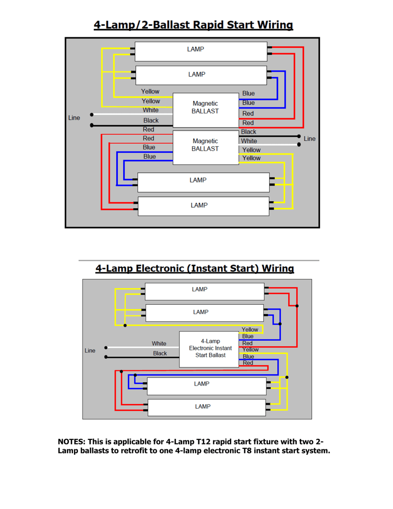
Notes This Is Applicable For 4 Lamp T12 Rapid Start Fixture With Two

2 T12 Ballasts To 1 T8 Ballast Running 4 Fluorescent Bulbs Doityourself Com Community Forums

Vc 6859 T12 Magnetic Ballast Wiring Diagram View Diagram Download Diagram

Wr 6457 T8 4n Ballast Wiring Diagram Free Diagram

Gz 3046 Wiring Diagram On Wiring Diagram T8 Fluorescent L Holder T12 To Wiring Diagram
Each component should be set and linked to other parts in specific manner.
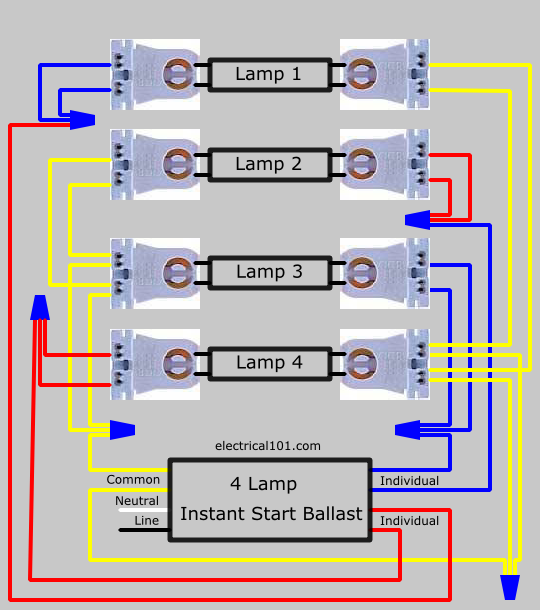
4 lamp t12 ballast wiring diagram. Parallel ballasts can only be wired in parallel according to the diagram on the ballast. Series ballasts can only be wired in series according to the diagram on the ballast. 2 lamp rapid start to. It reveals the components of the circuit as streamlined shapes and also the power and also signal connections between the devices.
November 30th t12 fluorescent tubes discontinued type of lamps that can be used with this ballast ballast wiring diagram 1. Otherwise the arrangement will not function as it ought. Philips advance ballast wiring diagram philips advance ballast icn 4s54 90c 2ls g wiring diagram philips advance ballast reb 2p32 n wiring diagram philips advance ballast wiring diagrams every electric arrangement consists of various different components. 35 4 lamp t5 ballast wiring diagram list how to replace two series ballasts with parallel t12 advance t8 schematic www ideas about additionally light diagrams fluorescent a2 2 e25 ch 2178.
Variety of 2 lamp t12 ballast wiring diagram. Changing the wiring on a. Wiring diagrams and descriptions to help you understand fluorescent ballasts a fluorescent tube circuit includes a ballast wires lampholders and the tubes. A wiring diagram is a streamlined conventional pictorial representation of an electrical circuit.
Type the wiring diagrams below should help in converting a 2 lamp t12 fixture to use t8 lamps. 4 lamp t12 ballast wiring diagram. Pay close attention to the wiring diagram on the ballast as the new electronic t8 ballast are wired quite differently from the old magnetic t retrofit wiring diagrams. It is important to note that t12 type ballasts have been discontinued due to poor mount the new t8 ballast in place and then start connecting the wires.
Collection of t12 ballast wiring diagram. Ge mvp t12 ballasts have the same wiring and mounting requirements as. By admin december 11 2017. Each part should be placed and connected with different parts in specific way.
It shows the parts of the circuit as simplified forms and also the power and also signal links in between the tools. Otherwise the arrangement will not function as it ought to be. This is applicable for 4 lamp t12 rapid start fixture with two 2 lamp ballasts to retrofit to one 4 lamp electronic t8 instant start. With some 3 and 4 lamp series parallel ballasts if a single lamp in one branch fails the lamp s in the parallel branch will continue to operate.
A wiring diagram is a simplified standard photographic depiction of an electrical circuit.

How To Convert A Two Ballast T8 Fluorescent Tube Light To Led T8 Double End Powered Fixture Youtube

Lutron Ec3dt4mwku1s Cfl Dim Ballast T4 4 Pin 120 277v 1 Lamp Lutron Ballast Cfl


Ge 120 To 277 Volt Electronic Ballast For Hi Output 8 Ft 2 Lamp T12 Fluorescent Fixture Feb Ballast Fluorescent Bulb Fluorescent

Pin On Light

Fulham 128 Watt 120 Volt Fluorescent Replacement Electronic Ballast Fulham Bulb Home Depot

This Led Emergency Ballast Installs Within The T5 T8 Lighting Fixture And Provides Emergency Lighting In The Event Of A Power Loss

Robertson 2p20135 Iea432t8120n B Quik Pak Of 10 Individually Wrapped Fluorescent Eballasts For 4 F32t8 Linear Lamps Instant Start 120vac 60hz Normal Bal Ballast Electrical Shop Electrical Jobs

2 Pickup Wiring Diagram New In 2020 Telecaster Overdrive Guitar Diagram

Led Tube Light Ballast Compatible With Ballast Only Book Now Led Tube Light Led Tubes Tube Light

How To Convert Fluorescent Lights Into Ballast Free Led Youtube Fluorescent Light Ballast Fluorescent

What Is A Ballast And What S It Got To Do With Led Tubes Led Tubes Led T8 Led Tube

Examples Of Prime Mover Control Systems Heat Recovery Gas Turbine Company Types Control System


