Diagram Old Vdo Tachometer Wiring
Vdo Tachometer Installation Manual
Https Www Manualshelf Com Manual Vdo Tachometer Installation Manual English Html

Vdo Tachometer Dip Switch Settings Ardusat Org
Vdo Tachometer Ybw Forum

Pin On Tachometer
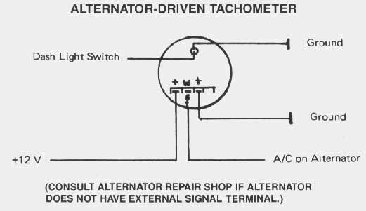
Diagram Denso Alternator Wiring Diagram Tach Full Version Hd Quality Diagram Tach Toggledwiring Contorock It
Click here for auto meter classic instruments defi or isspro instructions.
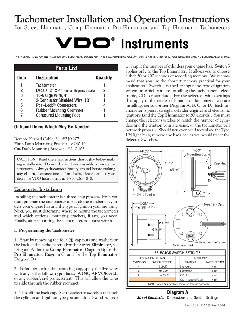
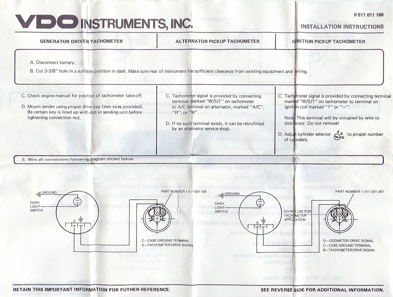
Diagram old vdo tachometer wiring. Please note that if you have a problem opening the pdf files just by clicking on the link please right click your mouse button over the file name and select save target as to your desktop. Measuring instruments vdo tachometer with counter installation instructions manual 11 pages measuring instruments vdo viewline tachometer without lcd product information 4 pages measuring instruments vdo contisys obd instruction manual. Old vdo tacho diagram. P 0 i.
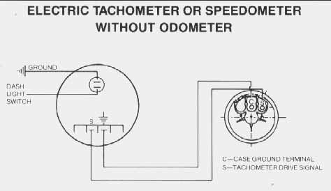
I ߑ 8 t z 8 on o o z c. I have the wiring dip switch diagram for 333 351 and 333 354 tacho s. Vdo rev counter wiring diagram diagram vdo rev counter wiring diagram posted on june 20 2018 by admin unusual vdo tachometer wiring diagram 1 min contemporary simple figure 4 17 dual synchronous rotor tachometer wiring diagram. 7 03 diagram b eliminator rf emi filter color code and hookup description note.
R r6 a s 1 g r v c 9 z u d ӧ y ef tc z n h i n מ. Adjust the potentiometer on the back of the tach. 8 pin connection f1 fuse 5a quick response c1 8 pin mqs connector you must comply with the. Fx wiring diagram tach wiring diagram 0 5 mustang tach wiring wiring diagram mega vdo tach wiring wiring diagram basic.
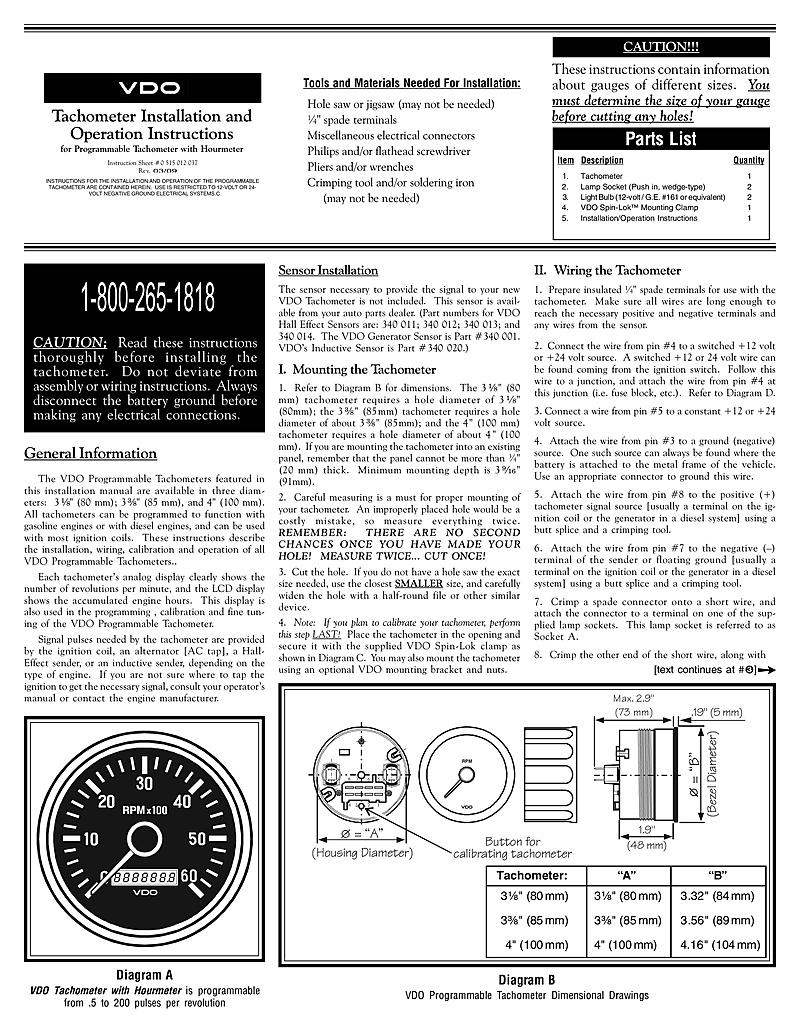
Part numbers forhe t vdo generator sensor is part 340 001 vdo s inductive sensor is part 340 020 1. Diagram a proper connection of the filter to the eliminator tachometer using the supplied butt splices part 0 511 012 332 rev. Related manuals for vdo tachometer. When following the wiring instructions in the main installation manual consider the wires from the filter as if they were the actual.
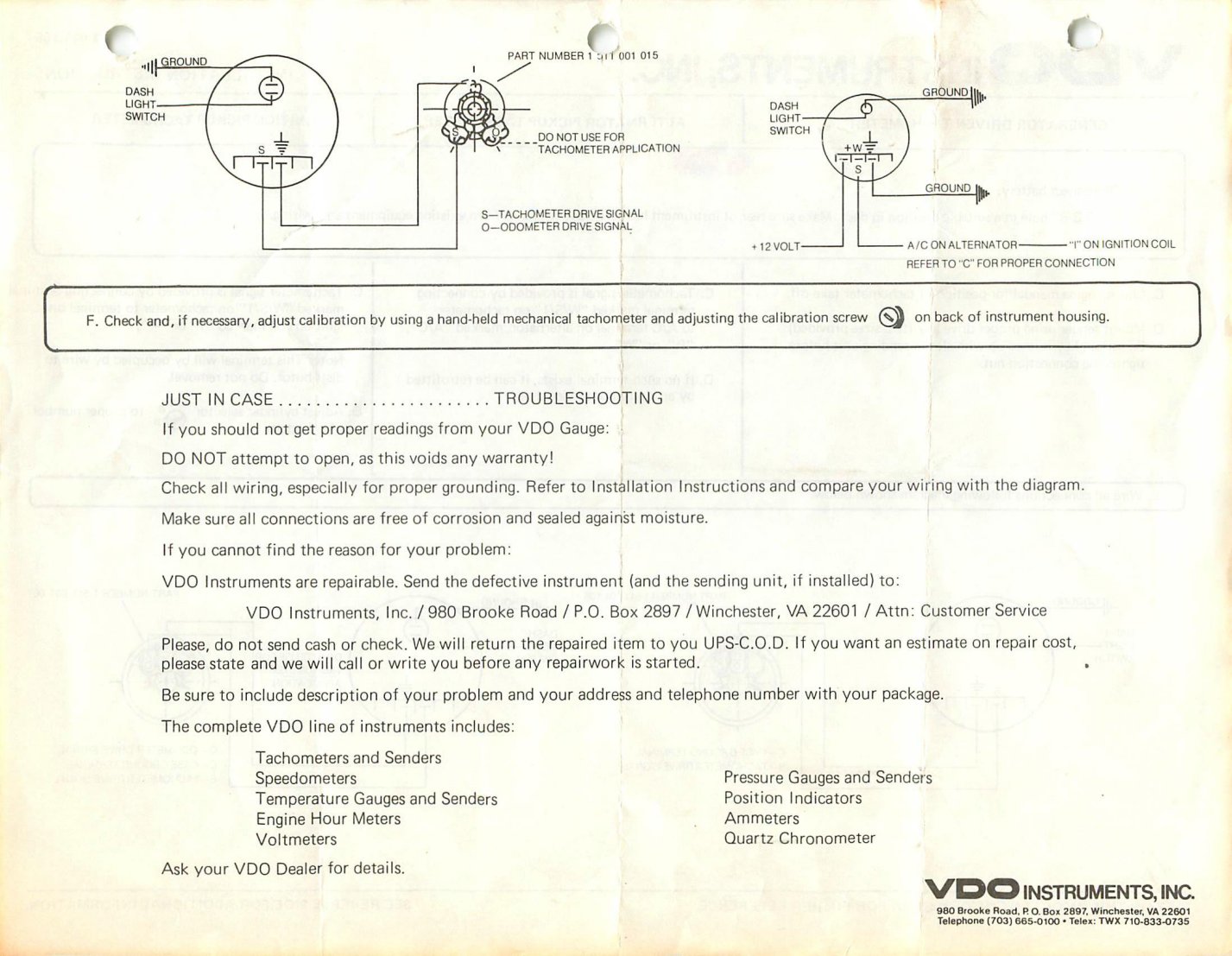
When the vdo tachometer reading. Diagram f fine adjustment of the vdo tachometer when used with an alternator compare the vdo tachometer reading with that of a reference tachometer. Vdo tachometer is not included. This sensor is avail able from your auto parts dealer.
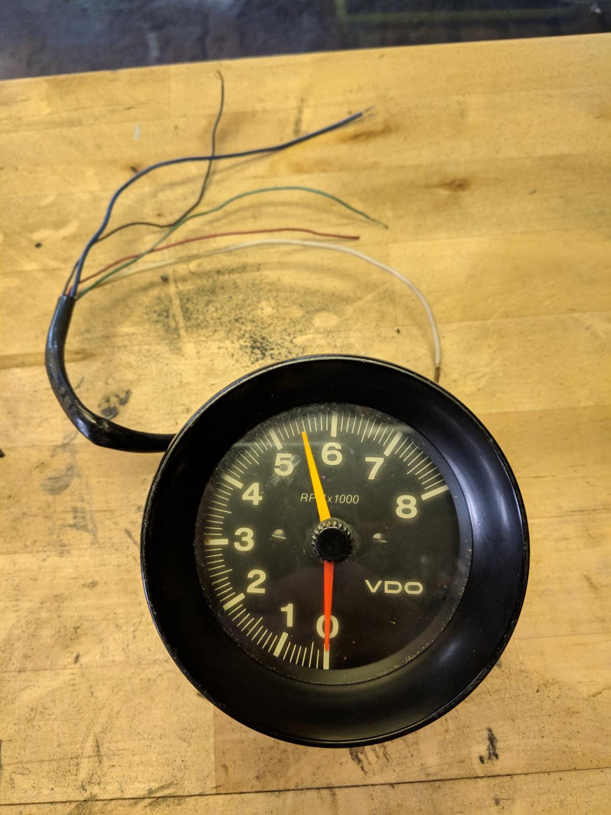
Diagram e proper wiring of the vdo programmable tachometer with typical ignition systems ˇˆ ˇ. I have this vdo tacho 80 odd mm unused but i have mislaid the instructions. Refer to diagram b for dimensions. Diagram f fine adjustment of the vdo tachometer when used with an alternator compare the vdo tachometer reading with that of a reference tachometer.
I tried it in my 300tdi it s out of my old race car but still reads high even after adjusting the internal pot. Adjust the potentiometer on the back of the tach. Rev counter wiring diagram another image. Tachometer without display 13 gb 14 connector set 8 pin a2c59510850 30 terminal 30 steady state plus 12 v 15 terminal 15 connected ignition plus 58 terminal 58 lighting 31 terminal 31 ground designations in the wiring diagram.
Diagram e proper wiring of the vdo programmable tachometer with typical ignition systems ˇˆ ˇ. When the vdo tachometer reading. I can scan it if it s the right one.
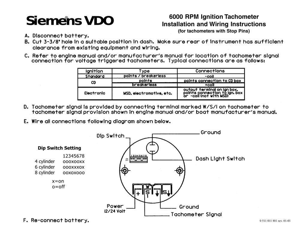
0 511 011 881a 6000 Rpm Ignition Tachometer Manualzz

Vl 9072 Tachometer Wiring Diagram Pro Get Free Image About Wiring Diagram Wiring Diagram

Wrg 2833 Diesel Tach Wiring

Auto Gauge Tach Wiring Diagram Free Download 2012 Volvo Xc60 Fuse Diagram Deviille Deco Doe3 Decorresine It
5efd Vdo 1318 Tachograph Wiring Diagram Wiring Resources

Vdo Tachometer Wiring Diagram 1 Min
Thesamba Com Beetle Late Model Super 1968 Up View Topic Vdo Tachometer Wiring Unable To Find Diagram
Vdo Programmable Tach With Hourmeter
Cc301 Vw Vdo Tach Wiring Diagram Wiring Library
Wiring Diagrams

Tach Troubles Pelican Parts Forums


