Motor Control Schematic Symbols

Types Of Motor Control Schematics Electrical Circuit Diagram Electronic Engineering Electrical Panel Wiring

Motor Control Fundamentals Wiki Odesie By Tech Transfer Vacuum Switch Electronic Schematics Electrical Symbols

Motor Control Fundamentals Wiki Odesie By Tech Transfer Pengelasan Belajar

Motor Control Symbols Electrical Engineering Projects Electrical Engineering Electrical Projects

A Motor Controller Schematic Motor

Single Phase Motor Control Wiring Diagram Electrical Engineering World Line Diagram Electrical Diagram Electricity
Motor whose field winding is in series with the armature winding is called dc series motor it is represented by this symbol in schematic designs.
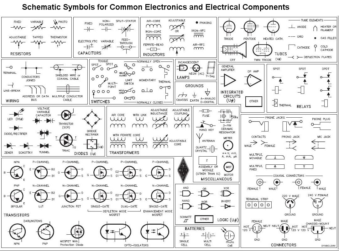
Motor control schematic symbols. One line diagrams are used when information about a circuit is required. Electrical symbols and line diagrams chapter 3 material taken from chapter 3 of electric motor controls g. These panels may be small as shown in figure 2 or very large as required to house the necessary. A motor converts electrical energy into mechanical energy.
This set of symbols is called the alphabet. Panel wiring techniques electrical control panels are available in all shapes and sizes to suit the particular requirements of the situation. Figure 1 typical wiring diagram. Students will be introduced to the differences between symbols used to represent electrical and control components.
The course discusses schematic symbols. Basic wiring for motor control technical data. Schematics and wiring diagrams are the written language of motor controls. Figure 1 is a typical wiring diagram for a three phase magnetic motor starter.
Rockis 2001 one line diagrams one line diagram a diagram that uses single lines and graphic symbols to indicate the path and components of an electrical circuit. Line diagrams show circuits of the operation of the controller. Unfortunately there is no actual standard used for motor control symbols. This is the symbol of a generic electrical motor that is used in electrical schematics.
Circuit symbols the following are the circuit symbols commonly used in motor related schematic diagrams. Schematic symbols is part four of the motor controls eight part training series. The manner in which symbols are drawn and interpreted will be discussed.

Electrical Engineering World Wiring A Motor Control Circuit Electrical Diagram Electrical Circuit Diagram Electrical Wiring Diagram

Electrical Symbols On Wiring And Schematic Diagrams Electrical Symbols Electrical Wiring Diagram Electrical Circuit Diagram

Plc Ladder Logic Symbols Motor Control Circuits Plc Programming Ladder Logic Electrical Circuit Diagram

Forward Reverse 3 Phase Ac Motor Control Wiring Diagram Electrical Circuit Diagram Circuit Diagram Electrical Diagram

Dol Starter Panel Wiring Diagram Save Start Stop And Motor Electrical Circuit Diagram Circuit Diagram Electric Circuit
Circuit Schematic Symbols Electrical Schematic Symbols Electrical Symbols Circuit Diagram

Plc Wiring Diagram Guide Ohiorising Org For Motor Control Panel Within Diagram Control Panels Paneling

Motor Control Wiring Diagram Electrical Circuit Diagram Electronic Engineering Electrical Panel Wiring

Anti Plugging Circuit Ladder Logic Electrical Circuit Diagram Electrical Diagram

Plc Ladder Logic Symbols Motor Control Circuits Plc Programming Ladder Logic Electrical Circuit Diagram

Symbols Of Electric Starter Motors The Motor Starters Are Devices Designed To Implement An Electric Motor Helping Electricity Electrical Symbols Electric Motor

Forward And Reverse Motor Starter Wiring Diagram Elec Eng World Electrical Circuit Diagram Circuit Diagram Electrical Diagram

Drawing Control On Off Delta Motor 3 Phase With Contactor Thermal Imagenes De Electricidad Diagrama De Instalacion Electrica Conductores Electricos


