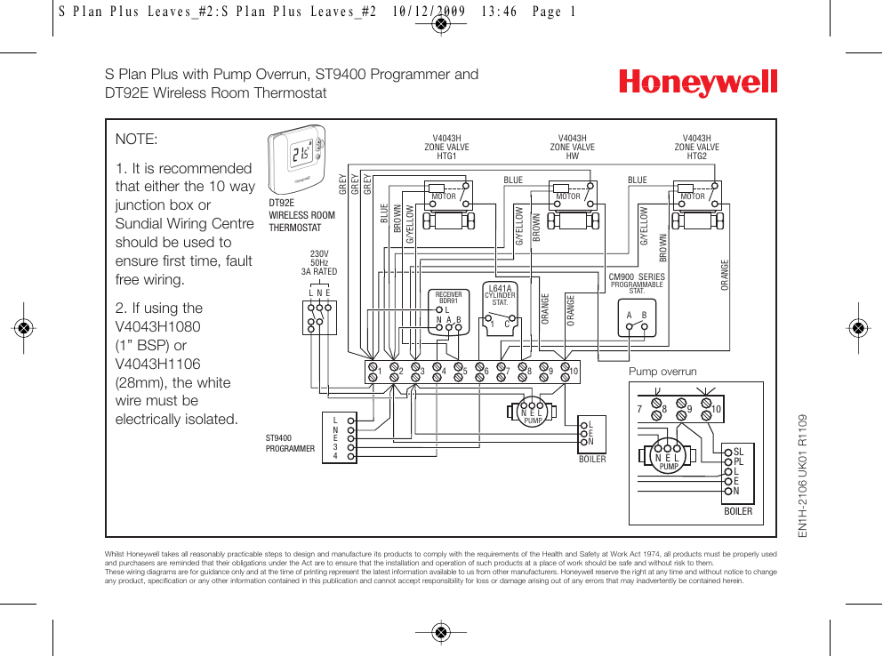
Motorised Valve Hive Dual Channel Wiring Diagram

It does close the valve completely.
Motorised valve hive dual channel wiring diagram. 11 02 2017 at 19 14. Yours is the only diagram that says how to do it. Dual channel receiver wiring. If heat is required power continues to terminal 5 in the wiring centre and operates the motor in the central heating valve.
How a mid position valve operates within a y plan heating system how a w plan heating system operates faq pump overrun wiring diagrams for s plan incorporating a st9400 programmer. I m changing my system boiler to a combi and would like to use my existing hive dual channel. This causes the valve motor to move to the mid position and water from the boiler flows to both the hot water cylinder and the radiators. You ll find a tether on the for conventional backplate to secure an earth wire if needed.
Our wiring diagrams section details a selection of key wiring diagrams focused around typical sundial s and y plans. This passes via the wiring centre terminal 4 to the room thermostat. S plan wiring centre cylinder thermostat hot water time clock auto bypass valve motorised zone valves and pipe stats are available if requested. Dual channel the hive receiver is double insulated so doesn t receiver need an earth connection.
Power starts at terminal 4 ch on in the programmer. Wundafloor does not supply. V4043 motorised zone valve the v4043 series of two port motorised valves has a wide range of flow control applications in domestic and light commercial central heating systems. As with hot water only the orange valve wire is connected to power via the wiring centre terminal 8 but orange is still not connected to anything inside the valve.
Once the valve is fully open a switch inside connects the grey and orange wires together.


