Ps1400 Emergency Ballast Wiring Diagram

Ar 7842 Collection Power Sentry Ps1400 Wiring Diagram Pictures Diagrams Wiring Diagram

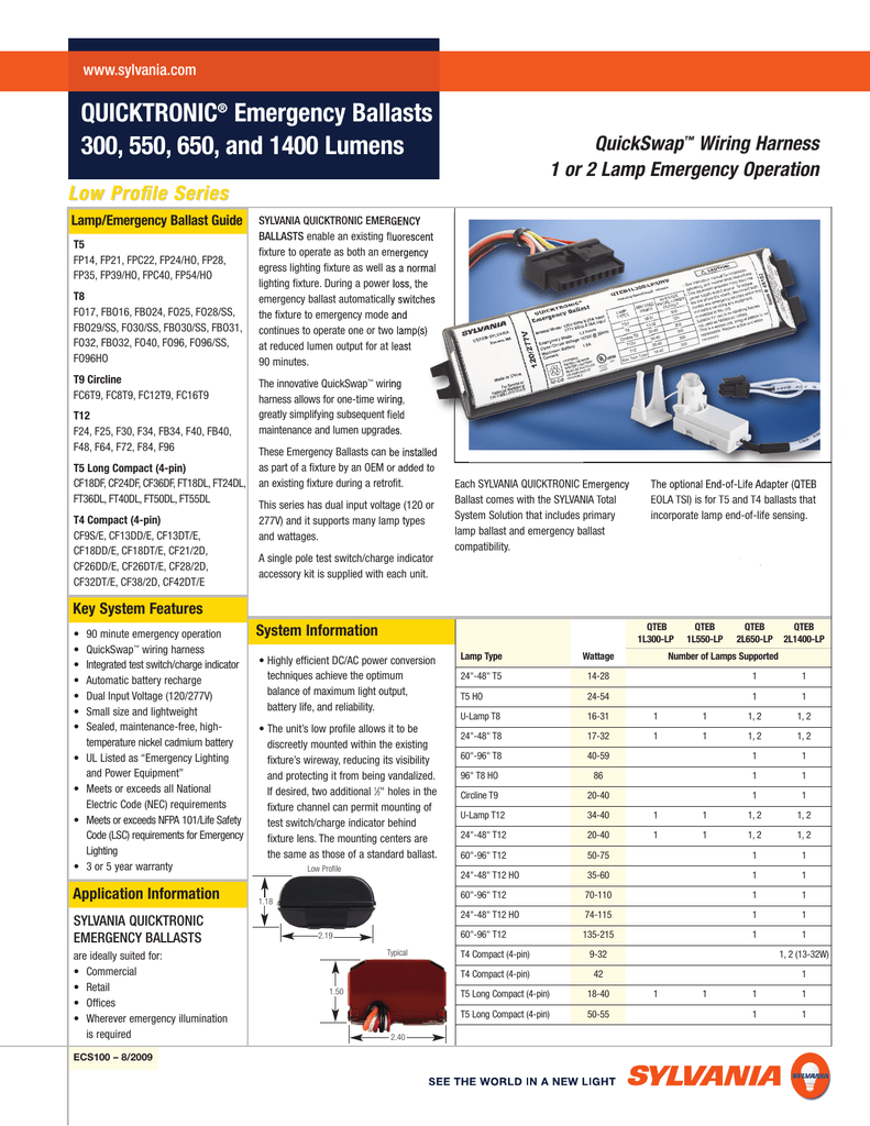
Ps1400qd Mvolt Fluorescent Emergency Ballast

Ry 4576 Ps1400 Wiring Diagram Free Image Wiring Diagram Engine Schematic Free Diagram

Nr 9032 Power Sentry Ps1400 Wiring Diagram Wiring Schematics And Diagrams Free Diagram
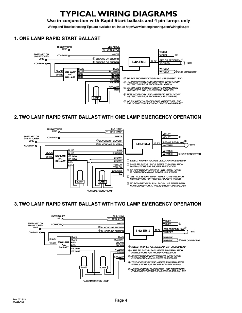
Diagram Power Sentry Ps1400 Wire Diagram Full Version Hd Quality Wire Diagram Pcschema Cribypopai Fr
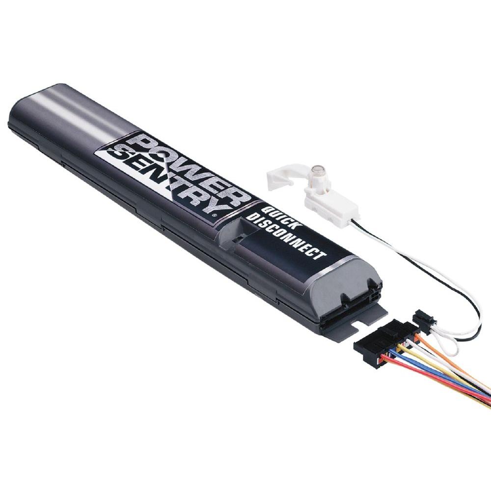
Lithonia Lighting Power Sentry Quick Disconnect Emergency Ballast For Fluorescent Fixtures Ps1400qd Mvolt M8 The Home Depot

May be used with other ballasts.
Ps1400 emergency ballast wiring diagram. Consult the factory for other wiring diagrams. Table 1 lamp base type t8 t9 t10 t12 1 1 1 single or bipin long compact 4 pin 2g11 diameter wattage. Assortment of power sentry emergency ballast wiring diagram. Wiring diagram for ps1400 wiring diagram xd 4310 ps1400 battery pack wiring diagram ps1400qd mvolt fluorescent emergency ballast lithonia lighting power sentry quick disconnect important sauards 1 read and follow all safety instructions ballasts electrical101 cm 1467 powersentry1400 4 lamp.
It shows the elements of the circuit as simplified forms and the power as well as signal links in between the devices. Specification grade emergency ballast to operate one or two lamps 4 or shorter or one 8 lamp. Ss 0400 ps1400 wiring diagram free image engine wz 2696 lithonia diagrams em ballast search mo 2897 power sentry psq500 4 lamp with options inde navy aa 3779 ps300 and 8ebd26 resources ps600 installation wire manualzz save these instructions ss 0400 ps1400 wiring diagram free image engine wz 2696 lithonia wiring diagrams em ballast wiring diagram search diagrams read more. A wiring diagram is a simplified conventional pictorial representation of an electrical circuit.
The standard ballast has a wiring diagram on it but an emergency ballast has many possible diagrams that are. Xd 4310 ps1400 battery pack wiring diagram ps1400qd mvolt fluorescent emergency ballast lithonia lighting power sentry quick disconnect important sauards 1 read and follow all safety instructions ballasts electrical101 cm 1467 powersentry1400 4 lamp with options inde navy psq500 ps600 installation wire diagrams manualzz pdf free 0ff294 resources xd 4310 ps1400 battery pack wiring diagram xd. Some electricians really struggle with them and replace the whole fixture rather than try to figure out where the problem is. Select the appropriate wiring diagram to connect the emergency ballast to the ac ballast and lamp.
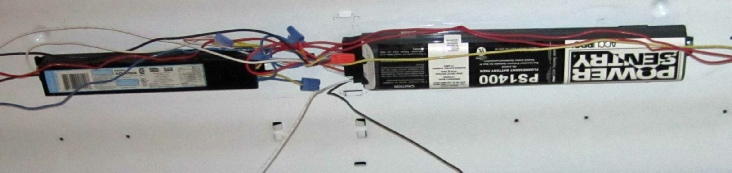
Variety of power sentry emergency ballast wiring diagram. Factory or field installed inside or outside field only fluorescent fixture to operate lamp s at a reduced light output providing optimum glare free illumination for a minimum of 90 minutes upon interruption of normal power. Remove the ballast channel cover and install the emergency ballast either in the ballast channel see illustrations 1 2 or on top of the fixture see illustration 3. Click on the image to enlarge and then save it to your computer by right clicking on the image.
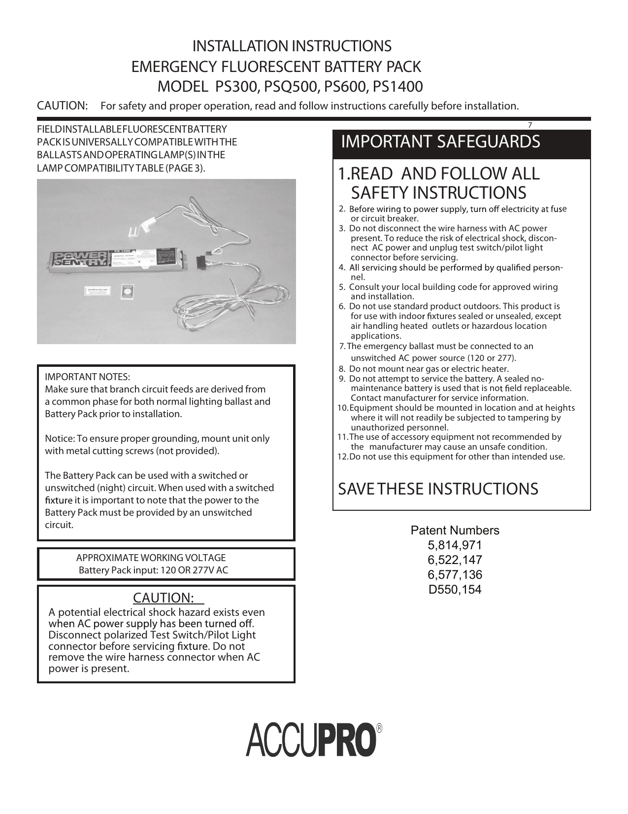
Disconnect ac power from the fixture. We would like to show you a description here but the site won t allow us. Emergency ballast wiring can be very complex and difficult to troubleshoot.

Lithonia Wiring Diagrams Auto Electrical Wiring Diagram
Psq500 Ps600 Ps1400 Installation Wire Diagrams Manualzz
Emergency Ballasts Electrical101

Ls 5079 Power Sentry Emergency Ballast Wiring Diagram In Addition Power Sentry Download Diagram

Emergency Ballast For Led Wiring Diagram

Diagram 480v Ballast Wiring Diagram Full Version Hd Quality Wiring Diagram Antiqueradiodiagrams K Danse Fr

Es 5248 Power Sentry Psdl3 Wiring Diagram Free Wiring Diagram Schematic Download Diagram

I Need A Wire Diagram For A Lithonia Ps300 W Power Inverter Fixya
Emergency Battery Ballast Wiring Diagram

Ka 8529 To One Switch Wiring Multiple Lights Download Diagram

Denko Lighting Pte Ltd Fl 120m Fl 140m Conventional Ballast

Psl600 Power Sentry Manualzz
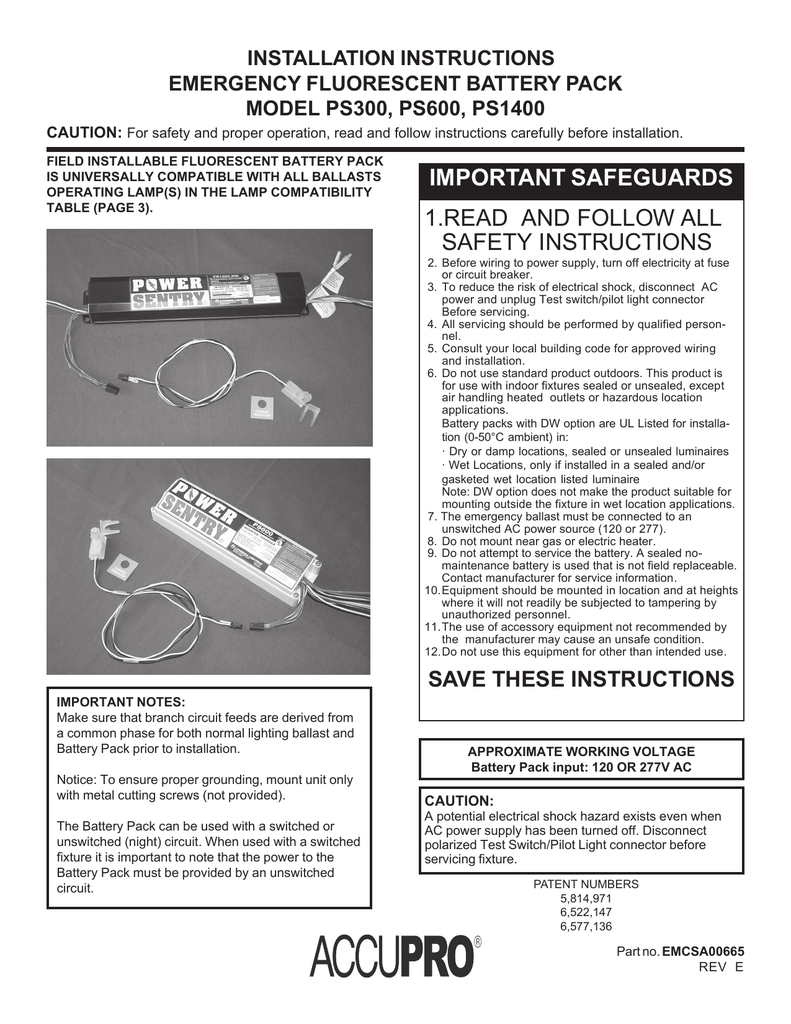
Important Safeguards 1 Read And Follow All Safety