Schematic Diagram Symbols And Meaning

Unique Wiring Diagram Symbols Meanings Diagrams Digramssample Diagramimages Electrical Schematic Symbols Electrical Wiring Diagram Electrical Symbols

Unique Wiring Diagram Symbols Meanings Diagrams Digramssample Diagramimages Electrical Symbols Electrical Wiring Diagram Electrical Diagram

Unique Wiring Diagram Symbols Meanings Diagrams Digramssample Diagramimages Electrical Wiring Diagram Electrical Diagram Electrical Symbols

Schematic Symbols Chart Wiring Diagram Database Wiring Drafting Symbols Electrical Schematic Symbols W Electrical Schematic Symbols Electronics Circuit Circuit

Schematic Symbols Chart Symbols Chart 1 3 Electrical Symbols Electrical Circuit Diagram Electrical Diagram

Automotive Wiring Diagram Symbols Electrical Wiring Diagram Electrical Symbols Electrical Diagram

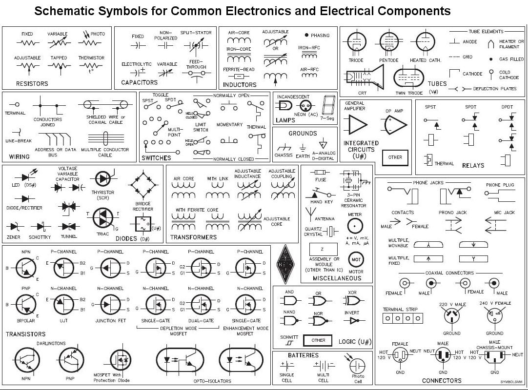
They are mostly used to draw a circuit diagram and are standardized internationally by the ieee standard ieee std 315 and the british standard bs 3939.
Schematic diagram symbols and meaning. Electrical symbols electronic symbols. Simple electronic circuits can have as little as two components. Click the icon of basic electrical to open the stencil that includes all symbols for making circuit diagrams. Electrical symbols and electronic circuit symbols are used for drawing schematic diagram.
A schematic diagram is a picture that represents the components of a process device or other object using abstract often standardized symbols and lines. Table of electrical symbols. Physical er models show all table structures including column name column data type column constraints primary key foreign key and relationships between tables. There are more than 30 symbols used in set theory but only three you need to know to understand the basics.
A schematic is defined as a picture that shows something in a simple way using symbols. Venn diagrams represent mathematical sets. This guide will walk you through the process of making a mathematical venn diagram explaining all the important symbols along the way. There are hundreds of different types of electronic components and each has its own unique schematic diagram symbol.
Yourdon and coad and gane and sarson. Physical er diagram symbols the physical data model is the most granular level of entity relationship diagrams and represents the process of adding information to the database. Note that when used. Making an electrical diagram becomes easy when you have access to thousands of electrical templates and symbols at your fingertips.
There are two different types of approaches to symbols in data flow diagrams. Electrical symbols are standardized throughout the industry so it is easy to achieve the ability to interpret the meaning of the symbols. In electronic circuits there are many electronic symbols that are used to represent or identify a basic electronic or electrical device. Schematic diagrams only depict the significant components of a system though some details in the diagram may also be exaggerated or introduced to.
Most electronic circuits will have additional components. The symbols represent electrical and electronic components. Fortunately you need to know only a few basic symbols and labels to get you started. An electronic symbol is a pictogram used to represent various electrical and electronic devices or functions such as wires batteries resistors and transistors in a schematic diagram of an electrical or electronic circuit these symbols are largely standardized internationally today but may vary from country to country or engineering discipline based on traditional conventions.
What are the symbols used in data flow diagrams dfd.
Circuit Schematic Symbols Electrical Schematic Symbols Electrical Symbols Circuit Diagram
Electrical Wiring Diagram Symbols Pdf Electrical Symbols Electrical Wiring Diagram Electrical Circuit Diagram

Wiring Diagram Symbols Chart Http Bookingritzcarlton Info Wiring Diagram Symbols Chart Electrical Symbols Electrical Wiring Diagram Circuit Diagram

Electrical Symbols On Wiring And Schematic Diagrams Electrical Symbols Electrical Wiring Diagram Electrical Circuit Diagram

Electrical Schematic Symbols Electrical Symbols Electrical Circuit Symbols Electrical Wiring Diagram

Elec 243 Tables Electronic Schematics Electrical Symbols Electrical Schematic Symbols

Wiring Diagram Symbols Automotive Http Bookingritzcarlton Info Wiring Diagram Symbols Aut Electrical Circuit Symbols Electrical Symbols Symbols And Meanings

The Most Popular Car Schematic Electrical Symbols Used In Automotive Wiring Diagrams Electrical Symbols Electrical Schematic Symbols Symbols

Electrical Circuit Symbols Gcse Physics Physics Revision Gcse Science Revision

Electrical Symbols13 Electrical Symbols Electrical Wiring Home Electrical Wiring

Electronics Symbols Components And Circuit Diagram Reading In Hindi Urdu Youtube Electrical Symbols Symbols Electronics Components

Electrical Circuit Symbols And Meanings In 2020 Electrical Engineering Projects Electrical Wiring Electrical Circuit Symbols

New Single Line Diagram Symbols Diagram Wiringdiagram Diagramming Diagramm Visuals Visu Electrical Wiring Diagram Ladder Logic Electrical Circuit Diagram


