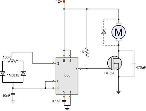
Simple Dc Motor Circuit Diagram

It is very simple and for large electric motors it involves the use of a shunt resistor modify this circuit diagram to include a meter that provides indirect indication of motor torque.
Simple dc motor circuit diagram. When voltage is applied current flows from power supply terminals through the series winding and armature winding. Question 1 how is it possible to electrically measure the torque output by a permanent magnet dc motor. In this post we learn how to make a simple 3 phase brushless dc motor driver circuit. An automatic starter operates in a similar fashion except that automatic relays short out sections of the starter resistance either by a time sequence or when the armature current drops to a selected value.
Figure 4 shows the automatic dc starter circuit diagram. The design of a simple motor speed controller using pwm may be understood as follows. Dc series motor circuit diagram in a series motor electric power is supplied between one end of the series field windings and one end of the armature. When it comes to controlling motor speed uniformly and efficiently a pwm based controller becomes the ideal option here we will learn more regarding a simple circuit to implement this operation.
Four point manual dc motor starter circuit diagram.


