Simple Series Circuit Diagram For Kids

Simple Circuit Project For Kids To Make Simple Electric Circuit Simple Circuit Projects Electric Circuits For Kids

Electrical Circuit Lesson Plans Basic Electrical Engineering Science Electricity Circuits Science

How To Draw An Electric Circuit Diagram For Kids Circuit Diagram Circuit Circuit Drawing

Series Simple Circuit For Grade 5 Series And Parallel Circuits Series Parallel Simple Circuit

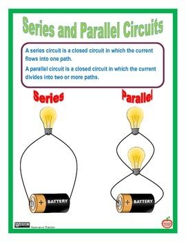
Parallel And Series Circuits Bing Images Series And Parallel Circuits Physics And Mathematics Circuit

Parallel And Series Circuits For Elementary School Google Search Series And Parallel Circuits Science Anchor Charts Elementary Schools

Some circuit diagram rules.
Simple series circuit diagram for kids. In this circuit we will try to connect three 5mm white leds in parallel and light them up using a 12v supply. There can be simple circuits series circuits supplying power to multiple electrical loads in one path. However the method we just used to analyze this simple series circuit can be streamlined for better understanding. Each component has its own symbol.
Electric circuits like ac lighting circuit battery charging circuit energy meter switch circuit air conditioning circuit thermocouple circuit dc lighting circuit multimeter circuit current transformer. The list of top10 simple electronic circuits discussed below are very helpful for the beginners while doing practice designing of these circuits helps to deal with complex circuits. Simple electronic circuits for beginners. Lesson for kids 3 36.
Here are ten simple electric circuits commonly found around the home. Diagram of a series circuit circuits can be drawn as lines and symbols. The circuit diagram for leds in parallel connection is shown in the following image. The supply voltage in a series circuit is equal to the sum of the individual voltage drops.
This super simple circuit project is perfect for adventures in science an elective adventure for webelos and arrows of light. Adventures in science requirement 3e create two circuits of three light bulbs and a battery. An electric circuit is a closed loop with a continuous flow of electric current from the power supply to the load. Circuit 3 of simple led circuits leds in parallel the final circuit in the simple led circuits tutorial is leds in parallel.
Construct one as a series circuit and the other as a parallel circuit. Component symbols in a circuit diagram are usually placed horizontally or vertically. The following are general circuit diagram rules. Wires or lines in circuit diagrams are usually horizontal or vertical.
In some cases a diagonal line may be used which is placed at 45 degrees. Analyzing simple series circuits with the table method and ohm s law. The battery creates the current in the circuit. We ve seen the symbols of the most common electrical components that are used to represent them.
A dc supply is used for a small led that has two terminals namely anode and cathode. In this video we will look at how to draw circuit diagrams. Wires connect the other components of the circuit.

Simple Electric Circuit Diagram For Kids

Electricity Circuits Worksheets Simple Circuit Elementary Worksheets Electrical Circuit Diagram
Series And Parallel Circuit Series And Parallel Circuits Science Electricity Science Fair Board

Circuit Diagram Maker Ks2 Diagram Diagramtemplate Diagramsample Electrical Circuit Diagram Circuit Diagram Electrical Diagram

Electrical Engineering Tutorial Resistance Series And Parallel Connection Electrical Projects How Electricity Works Electrical Engineering

Circuits One Path For Electricity Lesson Simple Circuit Circuit Diagram Circuit
Image Result For Electrical Circuit Diagram For Kids Electrical Circuit Diagram Circuit Diagram Electricity Lessons

Circuits One Path For Electricity Lesson In 2020 Electricity Lessons Circuit Simple Circuit

How Do You Draw Electrical Symbols And Diagrams Electrical Symbols Electricity Ks2 Science

How Simple Series Circuit Works Electronics Projects Circuits Simple Electronic Circuits Circuit Electronics Projects

How To Use A Multimeter Multimeter Series And Parallel Circuits Diy Electrical

Making Boys Men Simple Circuits For Kids Stem Projects For Kids Simple Circuit Circuit

Electric Circuits Worksheets Bundle Science Electricity Electric Circuit Science Education


