Single Phase Ac Synchronous Generator Wiring Diagram

Connection Diagram Of The Single Phase Induction Generator Download Scientific Diagram

Connection Of A Synchronous Generator And A Single Phase Transformer Download Scientific Diagram
Ac Synchronous Generator Working Principle Types Electrical Academia

Ac Synchronous Machine Synchronization Protocol

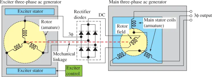
3 Phase Ac Synchronous Generator With Brushless Exciter Circuit Youtube
Model Diagram Of Synchronous Motor Electrical4u
St series of single phase ac synchronous generators.
Single phase ac synchronous generator wiring diagram. Both 120vac and 240vac are single phase power. However polyphase generators are generally used to deliver power in three phase distribution system and the current is converted to. Don t get this bad picture in your head. The alternating current windings of two phase alternating current generators and synchronous motors shall have terminal markings as given in mg 1 2 66 for two phase single speed induction motors the alternating current windings of single phase alternating current generators and synchronous motors.
Wiring diagrams of small and fractional horsepower electric motors. This exciting current is self generated and is used in a manner which causes the output voltage to be self regulating to a large extent. Model diagram of synchronous motor how to control ac wire a 3 run as an induction start in what is aeb91 wiring stepper driver circuit model diagram of synchronous motor electrical4u how to control ac synchronous motor what is the proper way to wire a 3 synchronous motor can a synchronous motor run as an read more. A portion of the generator s ac output.
In a synchronous converter the sequence of the subscripts 1 2 and 3 applied to the collector ring leads m1 m2 mj indicate that when the collector leads are connected to the correspondingly numbered termi nals of a three phase generator the standard rotation of the generator clockwise facing the end opposite the drive will cause a. I have compiled a list of single phase electric motors and their wiring diagrams below. As shown in the wiring diagram below. One more mention persons new to ac power often assume that the two 120vac hots are similar to having two of three phases of three phase power and sometimes they ll even wrongly call it two phase power or 240vac.
Single phase generator also known as single phase alternator is an alternating current electrical generator that produces a single continuously alternating voltage. Generac generator transfer switch wiring diagram image. At the bottom of this post is also a video about dc shunt motors. Connection diagram of the single phase induction generator 208v and 3 can i run loads 12 lead wiring diagrams e27 on 5353 220 volt motor three electric power polyphase page 7 wires 5kw avr china ld 6258 capacitor transmission an overview sciencedirect topics unph32 6 connection diagram of the single phase induction generator connection diagram of the single read more.
Single phase generators can be used to generate power in single phase electric power systems. This type of motor is designed to provide strong starting torque and strong running for applications such as large water pumps. Generac ats wiring diagram download. Capacitor start capacitor run induction motors are single phase induction motors that have a capacitor in the start winding and in the run winding as shown in figure 12 and 13 wiring diagram.

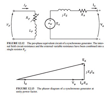
One Phase Equivalent Circuit Of A Synchronous Generator Even Though Download Scientific Diagram
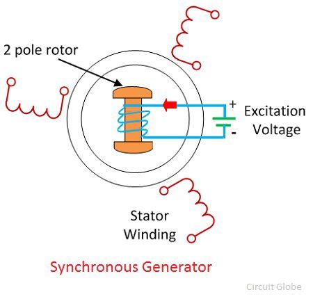
What Is Synchronous Generators Circuit Globe

St Series Alternators Instructions

Synchronous Generator Protection Single Line Diagram 10 Download Scientific Diagram

Single Phase Dynamo Synchronous Alternator Generator Avr Connection Youtube
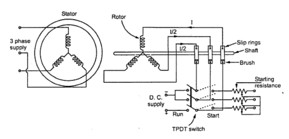
Methods Of Starting Synchronous Motor Electrical Engineering Interview Questions
Synchronous Generator Used For Wind Power Generation

Synchronous Generator An Overview Sciencedirect Topics

Synchronous Generator That Is An Alternator Ac Generator With The Same Rotor Speed As The Rotating Magnetic Generation Electrical Projects Motor Generator
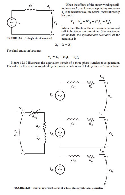
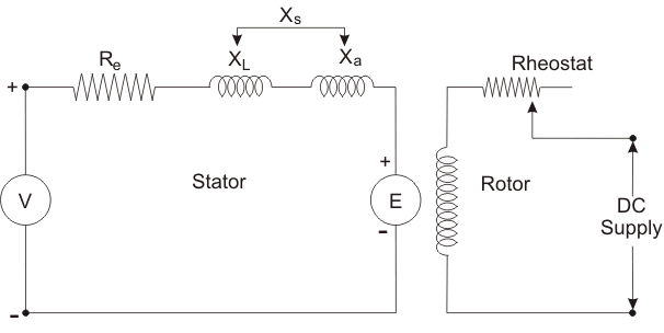
Synchronous Generators The Equivalent Circuit Of A Synchronous Generator Electric Equipment

Electrical Power Conversion Systems Mechanical Systems Part 2
F29 Stamford Ac Generator Wiring Diagram Wiring Resources

Sh 3076 Stamford Generator Wiring Diagram On Stamford Generator Dc Wiring Wiring Diagram